|
When considering fibre optic connectors for military and harsh environment industrial applications, the crucial issue is to keep the physically contacting heads of the fibres in a perfect cleanliness. It needs to be remembered, that the diameter of the light transmitting core of the fibre is 50µm or 62.5µm for multimode fibre (MM) and 9µm for single mode fibre (SM). To compare and recognise the scale, it needs to be quoted, that the average human hair has a diameter of 70-80µm. Any piece of dust that appears on the head of the fibre core is able to stop or significantly attenuate the transmission of the optical signal, and possibly, cause the permanent damage of the polished surfaces of the physically contacting fibres, what can result in a complete loss of the transmitting capabilities of the fibre connection. Standard, commercial fibre optic connectors, used in telecommunication or stationary infocom installations are not relevant for harsh environment military or industrial applications, for the following reasons:
- low protection against dust and particles,
- low or no protection against water and moisture, both connected and particularly disconnected,
- not possible to be mounted on the robust, harsh-environment fibre optic cables,
- low mechanical durability – the mostly used telecom connectors (SC, LC, MTRJ, etc.), have plastic-made bodies,
- difficult to clean, particularly the connectors on the cross-panel,
- no multiple channel solutions (with the exception of connectors with MT ferrules, but they are not applicable for other reasons),
- no availability of hermaphroditic solutions (for daisy-chain extensions of existing links),
|
|
- low resistance against vibration and mechanical shocks,
- low resistance against aggressive environmental factors (temperature shocks, salt spray, acid rain or atmosphere),
- high risk of mechanical damage,
- no possibility of receptacle and panel EMC protection,
- no connector-keying possibility (mechanical protection against mismatching the transmission lines on the cross-panel),
|
W przypadku światłowodowych złącz militarnych większość problemów opisanych powyżej została skutecznie usunięta. Poniżej opisano i pokazano na ilustracjach rozwiązania służące zwiększeniu odporności światłowodowych złącz militarnych na niefachową obsługę i trudne warunki pracy.
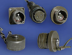 |
| MFM duplex connectors: variouis versions of receptacles (left and right), plug (middle) and cups (below). |
| |
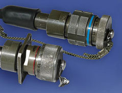 |
| MFM duplex connectors protected with caps. The caps can be fitted both with chains and nylon cords. |
| |
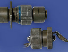 |
| Fully connected and environmentally sealed MFM duplex connectors. Caps are also locked when not protecting the connectors to stop dust and moisture intake. |
| |
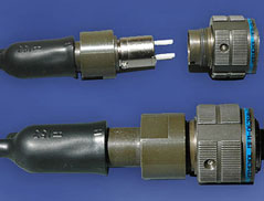 |
| MFM duplex cable plugs: connector prepared for cleaning (above), full access to the ceramic ferrules, connector clean and ready for service (below). |
| |
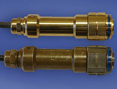 |
| Different versions (different metal) of the same TVOP connector: „Marine Bronze” (above), resistant to salt water and salt spray and standard, aluminium, cadmium coated (below). Scratches on the connectors are only visible sights of usage – they are not faulty damages, galvanic coating is still continuous and has all its working features. |
| |
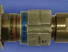 |
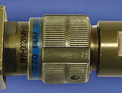
| MFM duplex connector not tight completely – red stripe visible |
| |
| |
|
|
- The connector features high resistance against the mechanical particles and dust intake, due to the usage of MIL-C-38999 series III derived shells, that deliver outstanding mechanical and environmental performance. When connector is completely locked and working, the connector is dustproof and watertight and can operate under 1m water immersion as a standard. When two sights of the connector are not tight, they are both protected with caps, appropriate for plug and receptacle sides. When the connector is locked and working, the caps are also locked together, to minimise the risk of dust ad liquid intake into the whole set.
- Easy to clean with simple tools, due to the construction of the connector – full access to the ceramic ferrules on the panel side, and quick and easy access to the ferrules in the plug, after unscrewing the outer shell. Possible to be dismantled, cleaned and completed for operation with bare hands and simple cleaning tools.
- High resistance to vibration and mechanical shock is provided with the standard locking mechanism of the MIL-C-38999 series III connector shell. Its design contains self locking mechanism, that not only stops unscrewing the connector, but also makes the connection more tight as much as the vibration is applied. A solid assembly of the body and shell is delivered in a cadmium coated aluminium as a standard. For more environmentally demanding solutions and applications, it is possible to deliver brass, marine bronze, stainless steel or composite versions of the connectors.
- A strong body and the outer shell enable robust mounting of the appropriate cable that is able to withstand 2000N tensile strength (that is 10-15 times more than the typical telecom connector solution). The proper military cable for military application features much higher flexibility and much smaller bend radius than the telecom cables. Another important parameter is the number of spooling cycles of the cable, again, much higher for the military cables, which by the nature of fact, are designed to be field deployable in a large number of times.
- The connector is “keyed”, that means is mechanically protected against mismatching the transmission lines. It is not possible to match connectors that have different keys, even between the same type of connectors - plugs and receptacles.
- To protect the connecting set against improper maintenance or incorrect plug-socket placement when being connected, the solution brings another important feature: scoop-proof. It is the protection against mechanical damage made with one side of the connector to the other. In other words, it protects the contacts (ferrules) not to be broken by the counterpart. Also, the usage of the caps with the chain or nylon cords raises the general quality and technical culture of the connecting set. The red mark on the connector indicates the proper tightness of the set – the stripe should not be visible when tight properly.
- MFM duplex set is 2-channel connector. The 4-channel MFM quad version is also available.
- The bodies of the panel and cable sides of the connector, as well as protective caps, are made of metal and coated with the conductive plating. That is why the MFM connectors deliver the electrical continuity for chassis screening and overall EMC performance of the system. Receptacles, both square-flange and jam-nut versions are designed to deliver high IP protection performance when mounted on the appliance or system panel.
- Hermaphroditic version of the MFM duplex connector is also available (HMFM). It enables daisy chains and extensions of existing patch-cords. For such version of the connection link, every face of the connector is the same and it is not necessary to apply the adapters in between the cables. It makes the cable and systems extensions easy and time saving. Very important feature when military, rapid field deployable systems are considered.
| |
|
|
 |
|
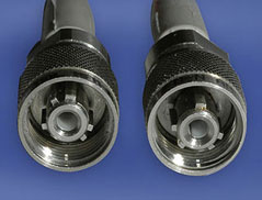 |
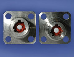
| Various keying of the same connector type. Here pictured, MFM simplex connector, made of the stainless copper-nickel alloy. Dark point in the middle section of the ferrule is the fibre of 125 µm diameter. |
|
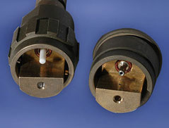
The same type of the connector (MFM simplex) with the different keys.
The white element in the middle section of the connector is the ceramic sleeve for axial positioning of the ferrules. |
| |
|
|
 |
|
 |
| MFM duplex connector tight completely and properly – red stripe not visible. |
|
Hermaphroditic version of the MFM duplex connector (HMFM). Cable plug uses (left) uses ceramic ferrule, receptacle (right) uses metallic ferrule for POF fibre. |
|
|


